Shadows
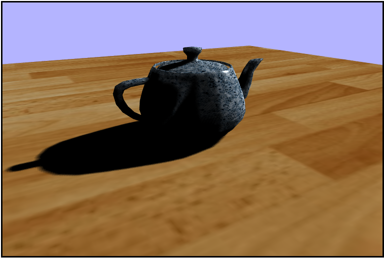
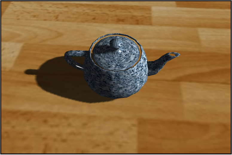
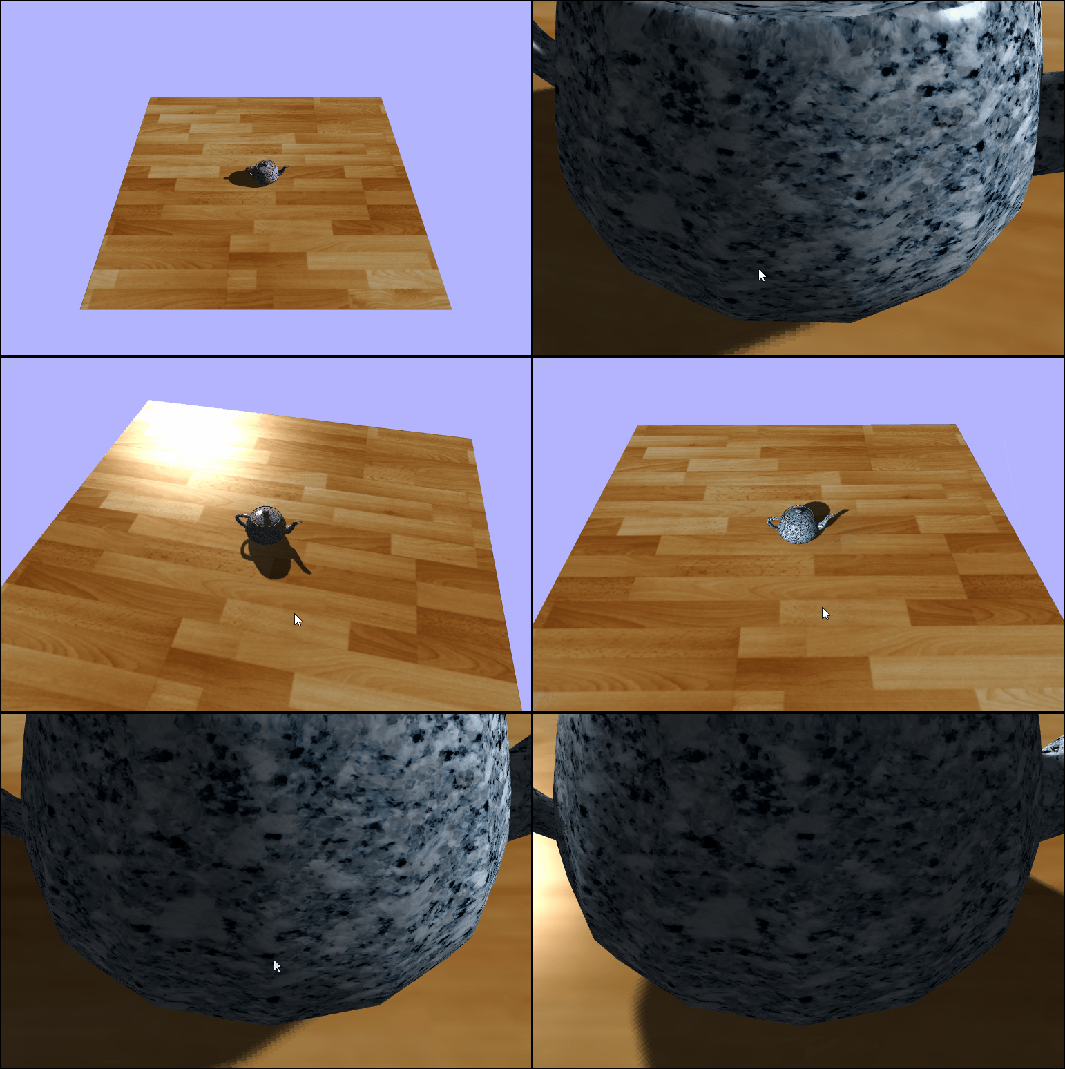
In ray/path tracing it is straightforward to get realistic looking shadows as they appear naturally in the algorithm. This is because in path tracing the objects are processed together withrespect to each light ray, so it is easy to determine if a pixel should be in shadow or not. Rasterization on the other hand, doesn't have this luxury as objects in the scene are processed independently of one another. This lead to the need for some other methods of processing to figure out real time shdows.
Shadow Volumes
The first method for defining shadows was to use shadw volumes. This method extrudes polygons from the existing geometry in the direction of the light. These volumes enclosed by these new polygons represent the areas that are in shadow from that object. Then these volumes are tested against the scene using the stencil buffer. Shadow volumes were used heavily in games from 2000-2010, but they are not used too much in modern games.
Shadow Volumes

Shadow Mapping
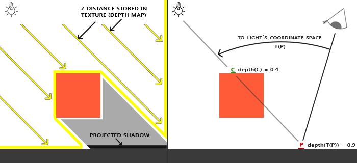
Shadow mapping is an image-based technique in which we store the pixel depth from the light source in a texture (shadow map) and use that to compare to objects in the scene whjen redering the final colors. This technique is used almost exclusively in modern games/game engines because it has more acceptable shortcomings than shadow volumes. The algorithm can be broken down into two steps: 1) Render the scene depth from the point of view of the light into a texture, and 2) Render the scene again from theeye and determine if each pixel is in shadow using the depth texture from step #1. The central question for step #2 is: is something occluding the surface from the point of view of the light? For this method, we'll need to make two passes on each render. The first pass we will want a view matrix on (or right around) the light source looking at the origin and we'll be storing the depth from the light to each fragment in an offscreen frame buffer which we can refer to later with a texture. Then on the second pass, we'll want to take care of rendering the final screen colors and we'll want to test the depth of each fragment against that stored in the shadow map. To do this, the world position also needs to be transformed into the light's clip space so that we can correctly compare the distances.
Shadow Mapping
Aliasing and Acne
One problem (or pair of) that arises with shadow mapping is aliasing and acne. They are a side effect of the orthographic projection not being at a nice angle with the surface. It looks like lots of sharp square edges and odd gaps in the shadow. Some easy ways to partially remedy this are to: add a bias offset, increase the shadow map resolution, or only render back faces (not facing the light camera) into the shadow map.
Shadow Acne
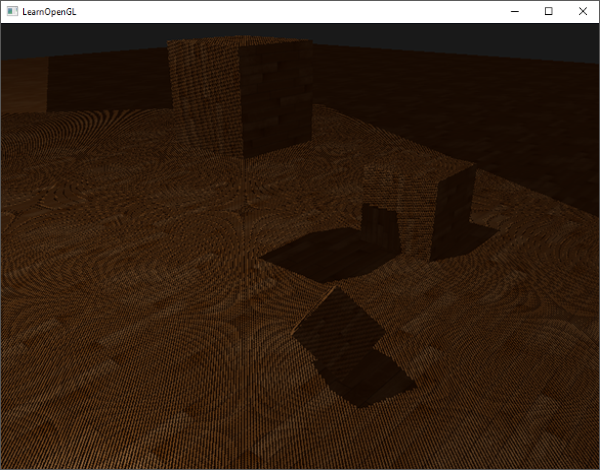
Without Bias

With Bias

Setting Up the light Camera
Since we are using shadow mapping, we are going to want to render the map as if the the view matrix was positioned on (or right around) the light and looking at the origin. For this we'll have a second camera known as the lightCamera and we'll use this camera's vew matix for our shadow pass to avoid having to move the real camera back and forth between passes. The last thing we need to make the matrix look at the origin is an "up" value which I belive is the surface normal of the ground plane but not sure. We'll want to manipulate the matrix from within the updateAndRender() function in order to account for the movable light.
var lightCamera = new Camera();

...

var lightTarget = new Vector4(0, 0, 0, 1);
var up = new Vector4(0, 1, 0, 0);
lightCamera.cameraWorldMatrix.makeLookAt(lightPos, lightTarget, up);
Now that we have our lightCamera set up, we are going to want to set up the projection matrix to be used in the vertex shader. Now, in the past assignments we have been using a perspective projection to take our geometry from view space to clip space, but for the shadow pass we want to percieve the light as directional; it should be the same at all surface points. So, we will be using an orthographic projection to preserve the parallelness of the light and avoid thewarping caused by a perspective projection. The dimensions of our frustum will be as follows: $Left = Bottom = 10;\ Right = Top = 10;\ Near = 1;\ Far = 20$.
shadowProjectionMatrix.makeOrthographic(-10, 10, 10, -10, 1.0, 20);And now that we have our camera set up for the shadow map, it's time to visualize the frame buffer using the SpectorJS extension as the shadow texture is just being rendered to an offscreen frame buffer for now.
Our texture sitting in a frame buffer
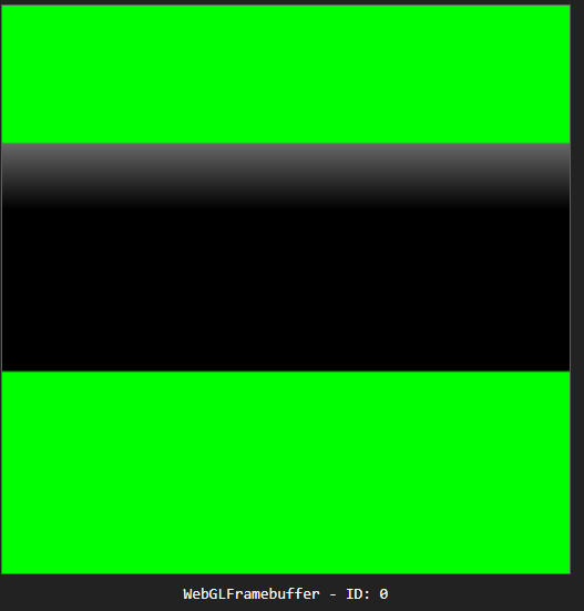
Visualizing the Depth Map (Texture)
Welcome to our final installment of Adventures in Fragment Shading. This week we'll be doing shadow
mapping!! To begin, let's start by remapping our depth values in the
depth-write.vs.glsl
out of NDC, the range $[-1,\ 1]$, to the acceptable color range for the fragment shader of $[0,\ 1]$. To
do this, we an simply half the value and adjust the minimum value by adding $\frac{1}{2}$ to the halved
value. If done correctly we should be able to see the outline fo the teapot in the frame buffer.
vDepth = gl_Position.z * 0.5 + 0.5;Frame 1
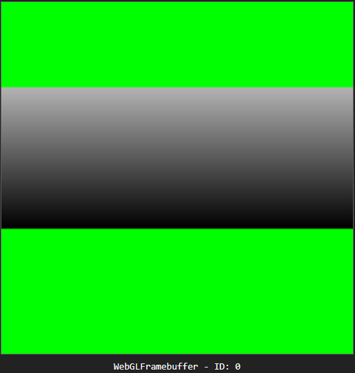
Frame 2
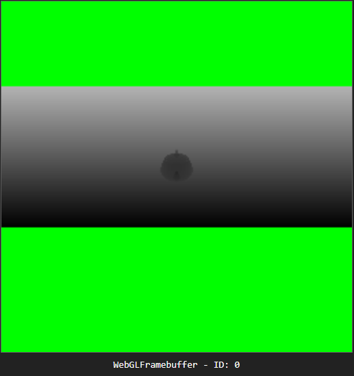
As a sanity check, let's make sure that we are able to see the texture from within the main shader code in phong.fs.glsl. For the moment, we'll use the normal $uv$ coordinates which are passed into the fragment shader as varyings just to see that we indeed have the correct texture.
vec4 shadowColor = texture2D(uShadowTexture, vTexCoords);That looks like a texture
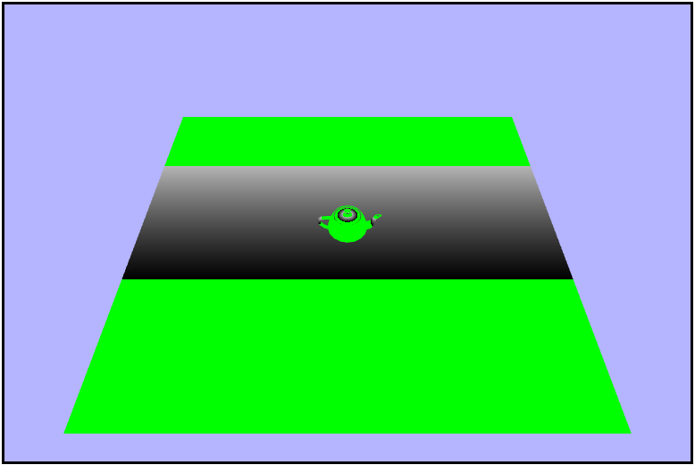
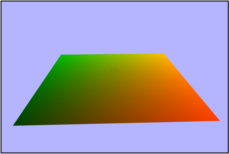
That last image didn't really show too much about what's really going on in the depth texure. We used the texture coordinates that were completely unrelated to the map which left most of the screen green as it was not in the view volume dring the shadow pass. So let's get the proper $uv$ coordinates for the light texture. Since we rendered the shadow map from withing the light's clip space, we'll need to transform each fragment in the phong shader into the light's clip space as well which will give us the NDC. From there, we need to remap to the range $[0,\ 1]$, and we can do iin the same manner that we did in the depth-write vertex shader. Visualizing the result we should see a green (left) to red (right) gradient across the scene.
// transform the world position into the lights clip space (clip space and NDC will be the same for orthographic projection)
vec4 lightSpaceNDC = uLightVPMatrix * vec4(vWorldPosition, 1.0);

// scale and bias the light-space NDC xy coordinates from [-1, 1] to [0, 1]
vec2 lightSpaceUV = lightSpaceNDC.xy * 0.5 + 0.5;

gl_FragColor = vec4(lightSpaceUV.xy, 0.0, 1.0);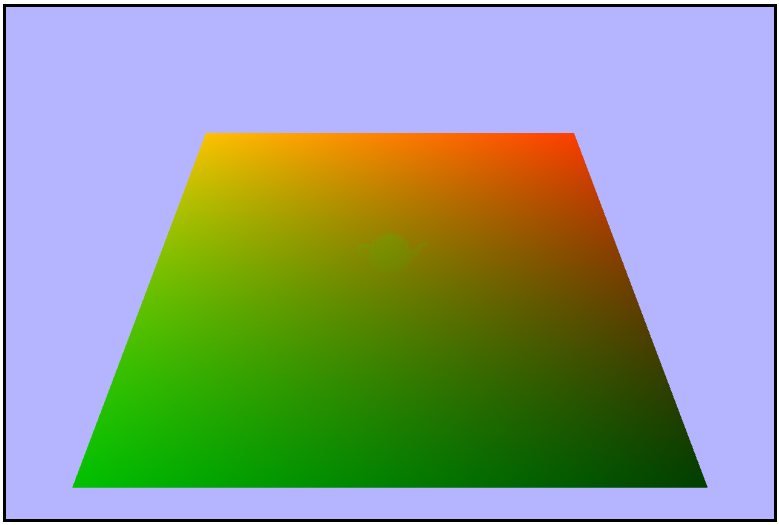
Aligning the camera with the light
Adding Shadows
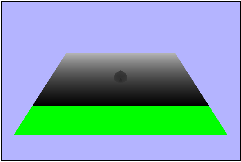
Now that we have our proper $uv$ coordinates for the shadow map, let's go ahead and sample that texture by itself. Notice how there is still a chunk of the plane that is green because it wasn't inside of the lights clip space.
vec4 shadowColor = texture2D(uShadowTexture, lightSpaceUV);

gl_FragColor = vec4(shadowColor.rgb, 1.0);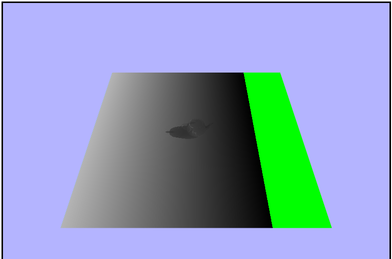
Aligning the camera with the light
The final piece we need in order to add the shadows is to get the depth of each fragment from the lightSpaceNDC ($z$ component). We then need to remap the depth value to the range $[0,\ 1]$ in the same way we did the lightSpaceUV coordinates. Visualizing the result we should now see that the green section of the plane is replaced by a black section.
float lightDepth = lightSpaceNDC.z * 0.5 + 0.5;

gl_FragColor = vec4(slightDepth, lightDepth, lightDepth, 1.0);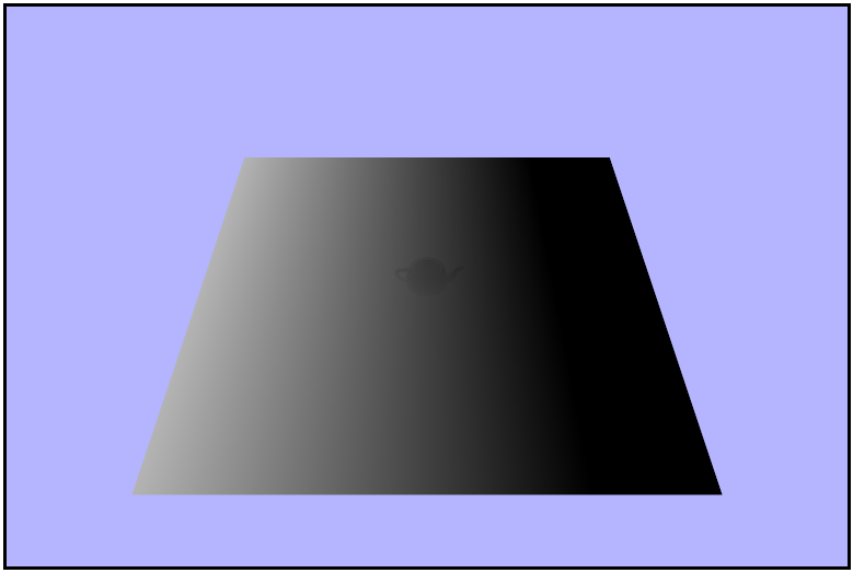
Aligning the camera with the light
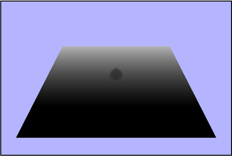
Now it's finally time to add the shados to the scene! We can do this by sampling the shadow map into a texture using the lightspace $uv$ coordinates and then checking if the $z$ or depth component of the texture is less than the light depth (distance from the light to the fragment). If the light depth is greater than the shadow texture depth, it means the fragment is in shadow and we should only add the ambient light contribution, oterwise we should add the full phong lighting contribution.
vec4 shadowColor = texture2D(uShadowTexture, lightSpaceUV);

if (lightDepth > shadowColor.z) {
    gl_FragColor = vec4(ambient, 1.0);
else {
    gl_FragColor = vec4(finalColor, 1.0);
}
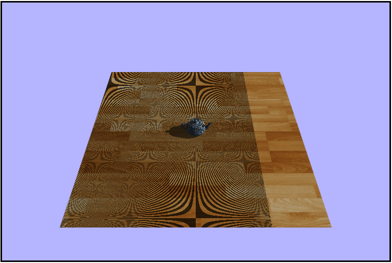
D: noooooo.. so much acne
Aligning the camera with the light
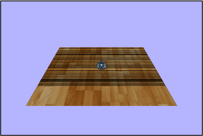
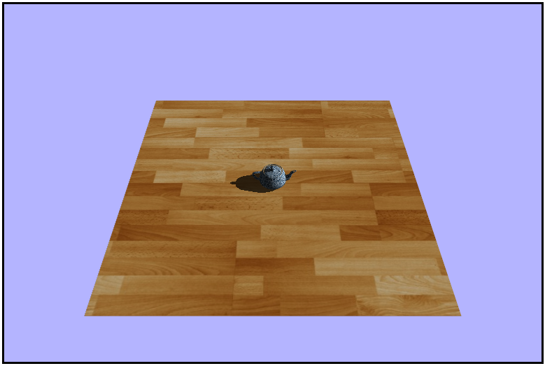
One last thing we need to account for is the surface acne cause by the orthographic projection not being at a nice angle with the plane in the scene. To remedy this, let's just add a small offset bias of $0.004$ to the value recieved from the shadow texuture and we should see that acne magically disappear.
if (lightDepth > shadowColor.z + bias)🎉
Smoothing the Shadows with PCF
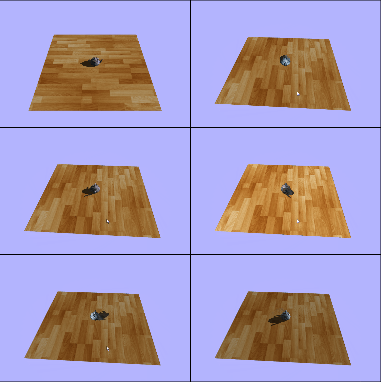
One problem with standard shadow mapping is that there is a very sharp edge to the shadows. This is due to the fact that each fragment is rendered as ether in shadow or not in shadow. This causes some blockyness as well as no fading/blending along the edges of shadows. One method to increase the fidelity of shadows, at the cost of some computing time, is to use Percentage Closer Filtering (PCF). PCF is very similar to Supper Sampling Anti Aliasing (SSAA) in that it takes samples from adjacent fragments on the texture map and esentially averages along them to decide what color wach fragmet should be. This allows the fragments in the middle of the shadow to remain completely dark and the fragmens outside of the shadow to remain normally lit. This will, however, cause the fragments along the edges of the shadow to blend to differing levels of shadowness by using what is known as the light factor. The light factor is just a percentage of which fragments in the sample are in shadow. The light factor is then applied to the diffuse contribution only, and I honestly am not sure exaclty why but when I was testing if added to the ambient or specular light the teapot seemed to be lit on the back where it should have been in shadow.
PCF

phong.fs.glsl
// distance any direction from the current texel
// 2 = 5x5 sample
const int pcfCount = 2;
// total texels sampled
const float totalTexals = (float(pcfCount) * 2.0 + 1.0) * (float(pcfCount) * 2.0 + 1.0);
// dimensions of the shadow map
// defined in createFrameBufferResources() in app.js
const float mapSize = 2048.0;
// size of a texel
// used to convert offsets to proper size
const float texelSize = 1.0 / mapSize;

void main(void) {
    ...

    // number of samples in shadow for the fragment
    float total = 0.0;

    // loop over the adjacent samples
    for (int x = -pcfCount; x <= pcfCount; x++) {
        for (int y = -pcfCount; y <= pcfCount; y++) {
            // is each sample in shadow?
            // making sure to convert each relative coordinate pair to texel space
            float nearest = texture2D(uShadowTexture, lightSpaceUV + vec2(x, y) * texelSize).z;
            if (lightDepth > nearest + bias) {
                total += 1.0;
            }
        }
    }

    // set the percentage of light we think the fragment should be in
    total /= totalTexals;
    float lightFactor = 1.0 - total;

    vec3 ambient = vec3(0.2, 0.2, 0.2) * texColor.rgb;
    vec3 diffuseColor = texColor.rgb * lambert * lightFactor;
    vec3 specularColor = vec3(1.0, 1.0, 1.0) * specularIntensity;
    vec3 finalColor = ambient + diffuseColor + specularColor;
    gl_FragColor = vec4(finalColor, 1.0);
}
lightFactor appliead to finalColor. Notice how the shadow is split.
